The Dirt Bike
THIS PAGE IS STILL UNDER CONSTRUCTION
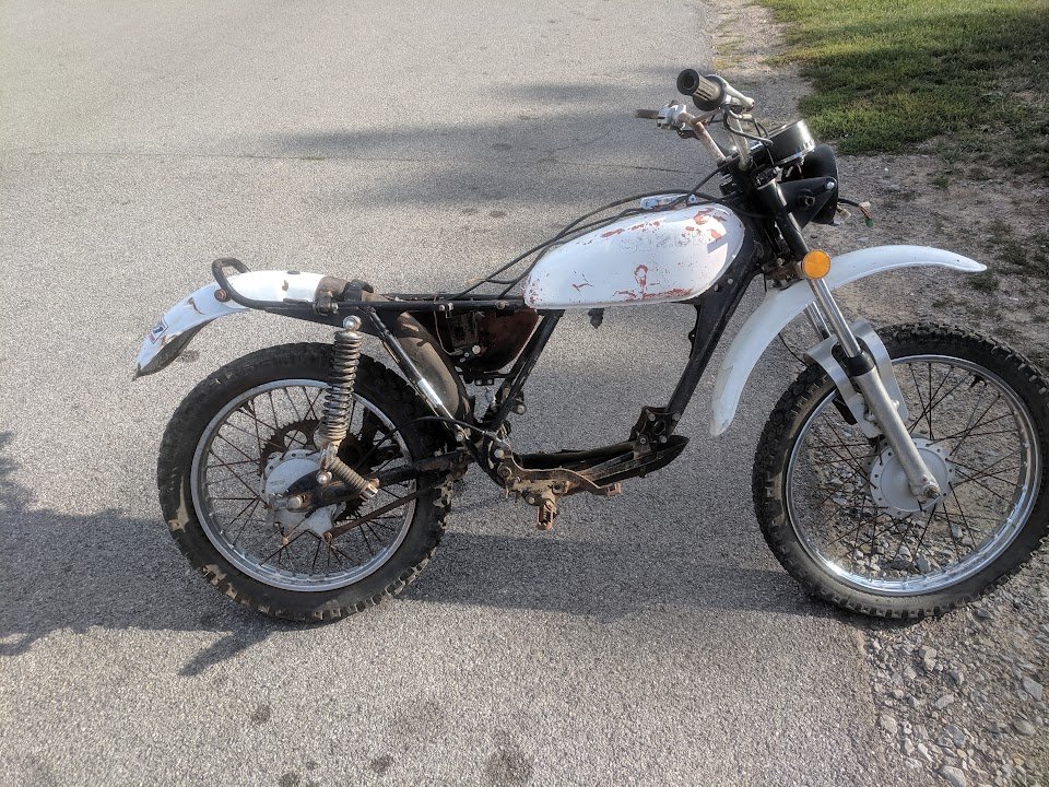
It was my freshman year of College at RIT, and immediately, I wanted a project. Something that was truly engineering. Gone were the days of being best friends with an angle grinder (Especially because I was living in dorms). I wanted this project to utilize CAD, and be manufactured in a way that could be considered mass producible; who knows, if this became something that enough people wanted, they could take the files and get parts made. Anyways, I went onto Facebook marketplace, and found a stylish vintage dirt bike, a 1976 Suzuki TS125 for 100$.
Goals
Build a minimally intrusive conversion assembly
Have the project documented in CAD
Make the battery hot swappable, I want to be able to use this bike at all times, so a spare battery at home charging would be ideal
Clean end result, minimal welding, cutting, no specialized fab tools
Responsibilities
Get this project done
Don’t break the bank trying to finish the project
Make it look good, if I am going to look cool riding it, the bike should probably look cool too.
Time Line
September 2019 - Who knows when, I am still chipping away at this project (as of March 2023)
Freshman Year (1st Year)
First Iteration
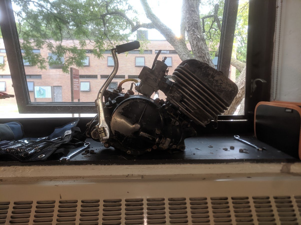
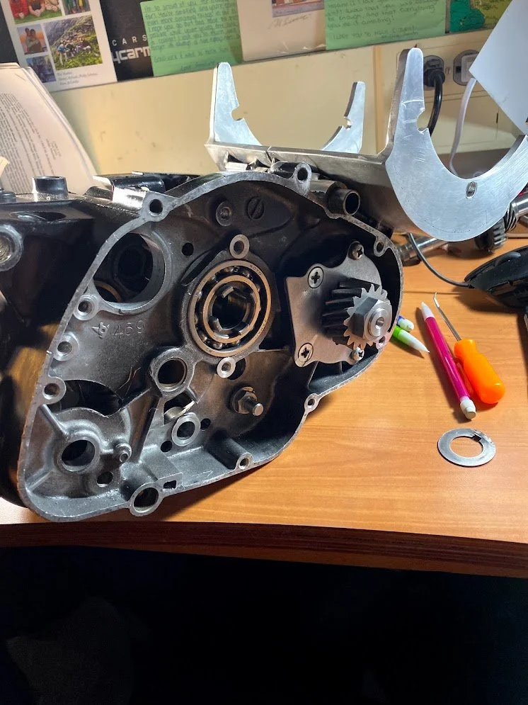
I figured that it would be best to use the existing gearbox, I could really take advantage of the high RPM’s, and low current for inclines. This was later scrapped for reasons I will explain later, but I think it would be fun to explain my questionable thought process and approach. Here is the Gearbox cracked open, I inspected all the teeth, and for the most part they looked good enough to handle 10 or so kilowatts and some absurd amount of torque.
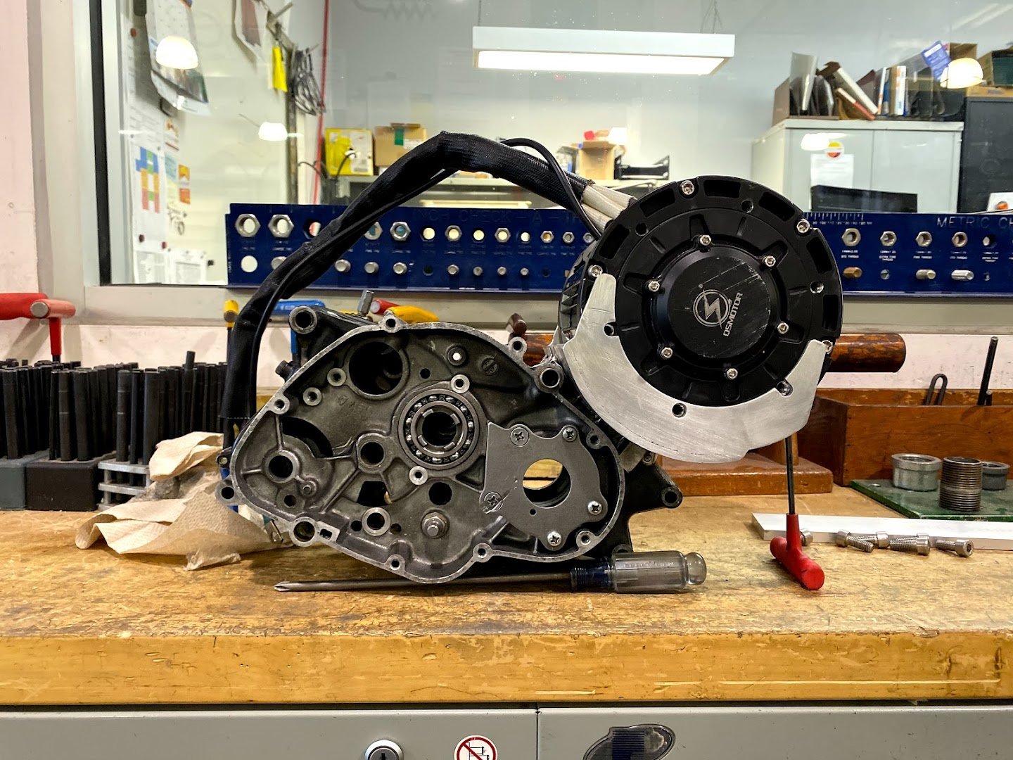
The location of choice for the motor, and subsequently the cradle, is where the cylinder head used to be. No internal combustion, no cylinder/ cylinder head, therefore newly acquired real-estate in a fairly small frame. I made some modifications to the transmission case/ engine case. I’m not really sure what to call this Frankenstein-esque creation. I whipped up some motor cradle plates in SolidWorks, cut them out, and welded them into place.
The attentive individual will notice a large scallop cut into where the cylinder used to live. This was done to try to lower the center of gravity, and make this whole unit as compact as possible. The was the scallop was cut was using a fly cutter on a Bridgeport mill. Here you can see how I set it up, trying to get the arc accurately placed relative to the transmission case. The arc is better define by the piece of sheet metal placed inside (bent on a sheet metal roller).
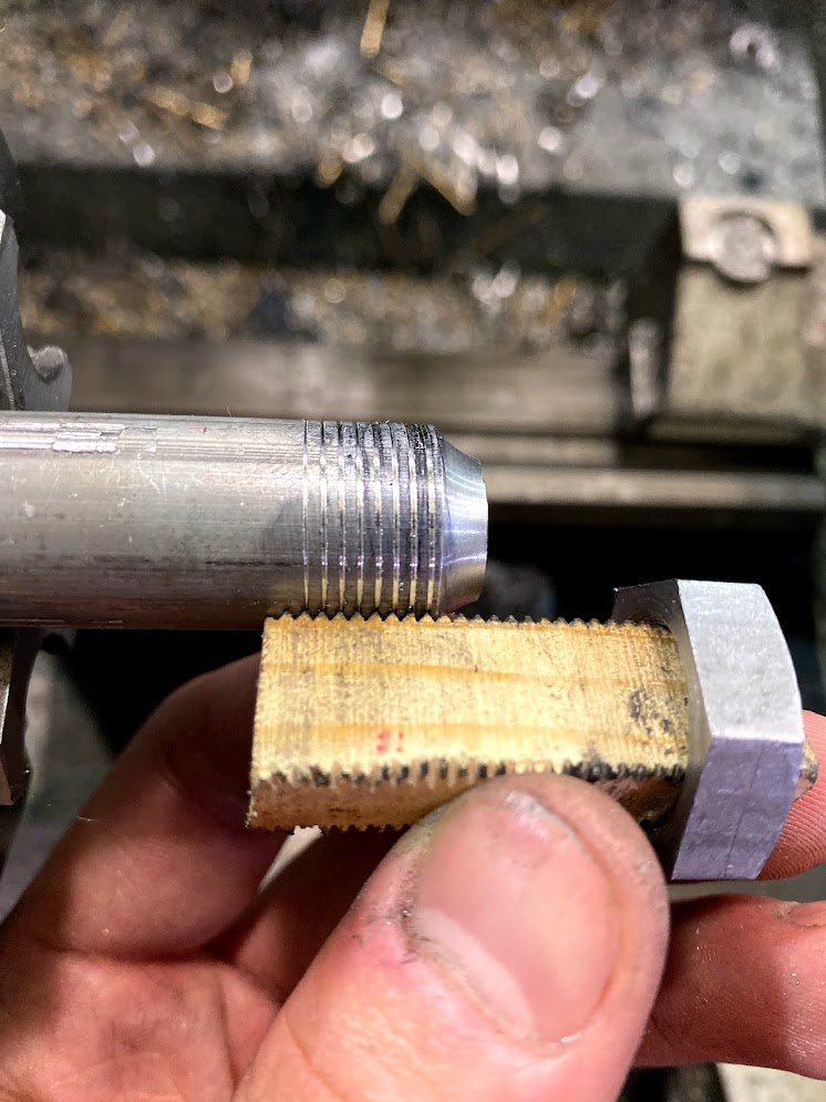
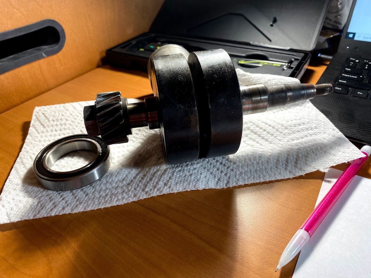
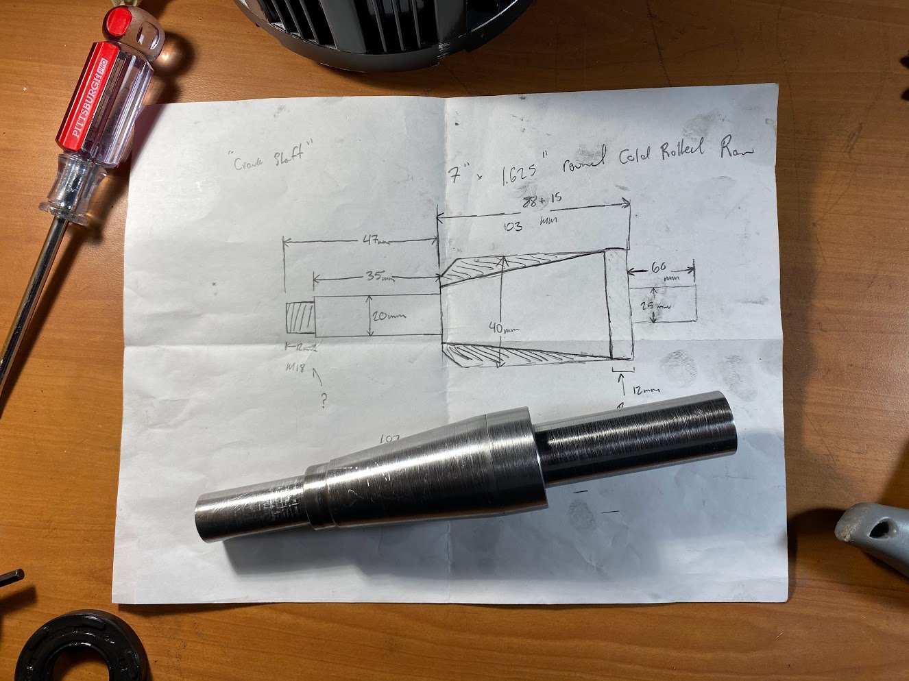
Lastly, I turned a replacement crank shaft, that would act as a jackshaft, to allow power to be brought in by the motor, and run through the transmission. Below are some photos going through the turning of the shaft, and preliminary assembly. Below are some photos of that progress, Installed crankshaft replacement, motor mounted, and how I intended for the gearbox to still be serviceable despite being modified. I included a side profile of the original powerplant as a comparison of what I attempted to achieve, if anything, this was a lateral move, instead of improvement. Looking back, I realize I didn’t CAD this shaft, oops. All this would be for nothing, as COVID19 would quickly send me back to California for the remainder of the year and Summer. During this time home, I had much time to reflect on the progress I had made, and I was left with the realization that my current approach was not a smart way to go about this. At the very least, I learned a lot about how motorcycle/ sequential gear boxes work, and picked up a few mechanism ideas to potentially implement in my work later.
Sophomore Year and Junior Year (2nd and 3rd Year)
Second Iteration
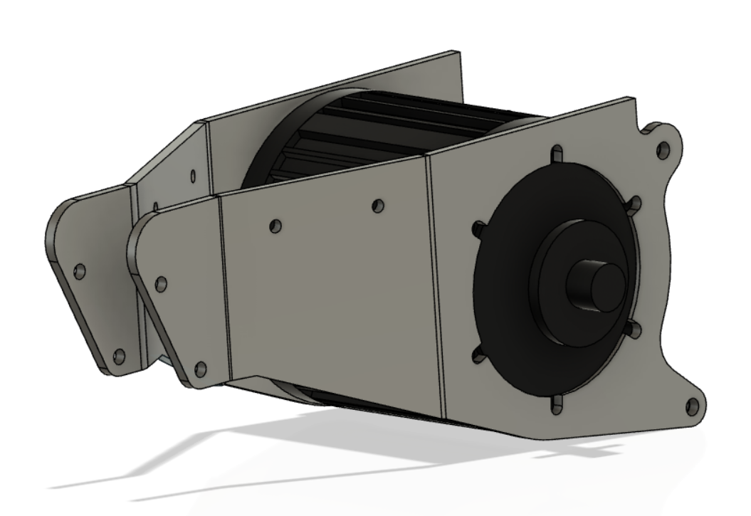
All that talk about using the gearbox was no longer a good idea, I would now be using the motor in such a manner to maximize efficiency with a straightforward chain drive. The parts for the majority of the build should use laser/ plasma cut plates, something that is very easy to produce, and with the correct orientation, very strong. It was a round this time I learned about a company called SendCutSend. They are a CNC laser cutting service, able to work with a variety of materials and thicknesses, and also do CNC bending.
I used the cannibalized halves of the gearbox to draw out the important mounting points, in an attempt to recycle the existing mounts on the frame. These would then be transferred into CAD. I could not find a model of the motor I had chosen, so I made a simple body as a placeholder. The drive shaft of the motor was strategically placed in the same axis/ location as the output shaft of the gearbox, so as not to fiddle with the designs settled on by 1970’s Suzuki Engineers.
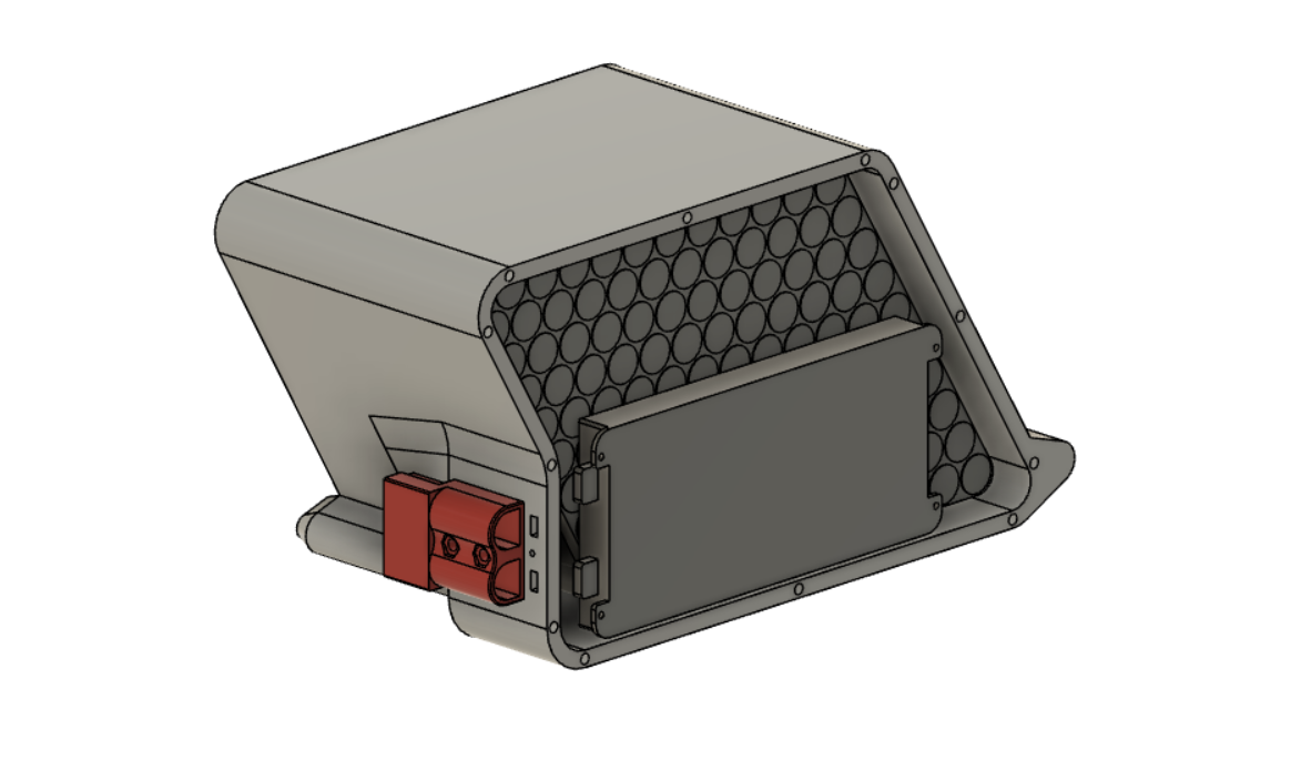
In addition to this moment of design clarity, I finally found which batteries I wanted to use, while on CO-OP in California. a little over 200 Sony VCT5 18650 cells. In a 20S14P configuration, I could draw about 280 amps continuous. I likely wont be going over 200 amps peak, but it is nice to know that I wont be bottlenecked by the batteries internal resistance. I designed an enclosure around these cells that also fit the flow of the frame. In addition to the 18650 Cells, I needed to enclose a BMS (Battery Management System). Below is the somewhat unusual shape I decided on to allow for the fitting of everything. I somehow would have to make this a removable unit, preferably with a connector that mates with the installation. I forget the specific term for this, but cordless tool batteries famously excel at this.
The next step was to figure out how to combine the Battery enclosure and the motor mounts. This really was the key to making this succeed. Unlike in the past, where I would have to plug in a connector, putting strain on wire and hurt my fingertips if it was cold out, I wanted this to be easy and simple (in both use and production). Much of the CAD seen above is the result of refinement over time as a result if realization that I needed something, or there was too much material in this spot, this gets in the way of my foot etc. To ensure the Image of this setup would not be disrupted and to ensure fit within the contextual frame, I found a good side profile image of the same dirt bike, and brought it into the CAD workspace, aligning the mounting holes with my motor plates. This gave me some context for the remainder of the design.


