The Dirt Bike
THIS PAGE IS STILL UNDER CONSTRUCTION
I was about to go into my final summer as a college student, and had some ideas of building an electric minibike at home in California. I was quickly convinced to spend a little more money and just build a full size motorcycle/ moped that would be safer, have greater range and look better for a small increase of price. How hard could it be?
Goals
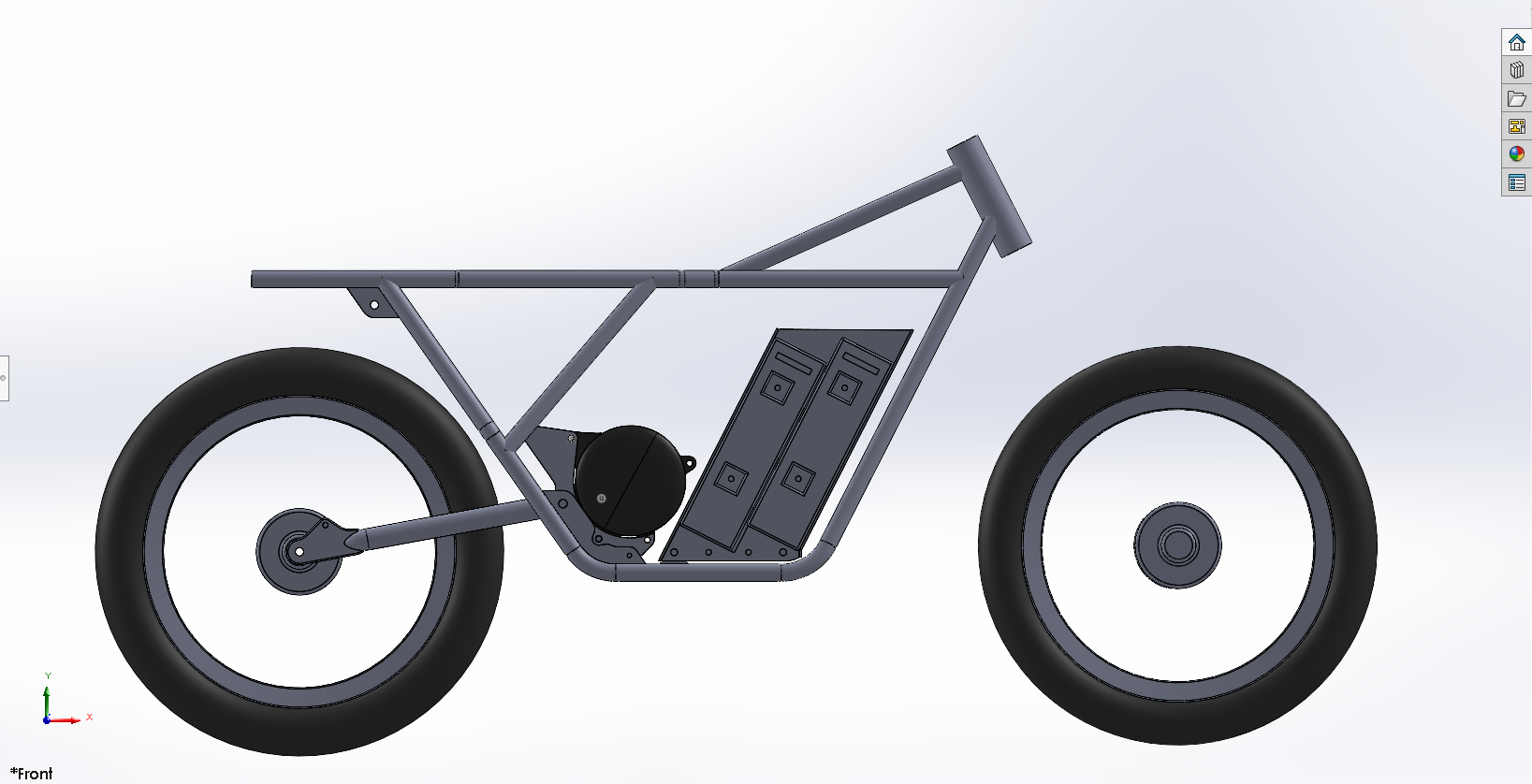
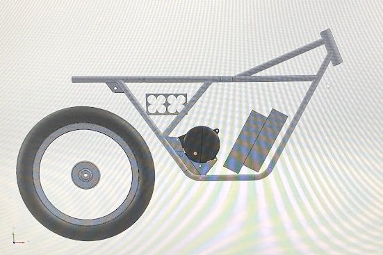
Design the whole project in CAD prior to construction
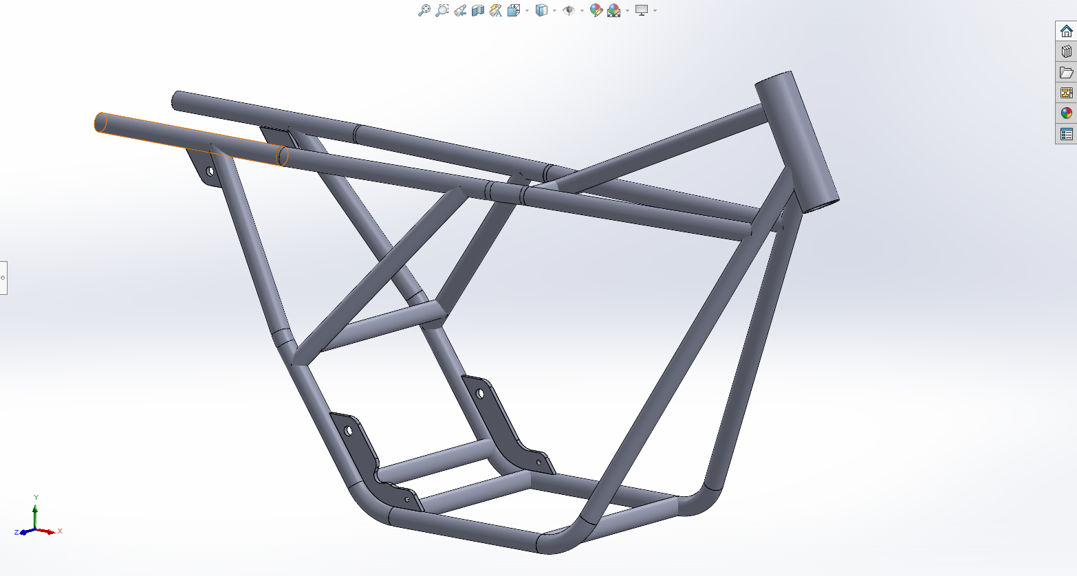
Custom tube frame design
Be able to ride the bike from Palo Alto, CA (where I live) to Halfmoon Bay, CA (where the beach is)
Use off the shelf parts for consumables and where possible (no custom drums or hubs, keep it simple, no re-inventing the wheel)
Responsibilities
Get this project done quickly
Have an ease of maintenance power system.
Have power and range comparable to an existing shipping product (I want people to think that I bought this)
Time Line
May 2023 - Its not done yet, but there has been great progress.
Summer 2023 (my last summer as a college student)
Planning Stage
If my goal was to use as many off the shelf components as possible, then it would not be a bad idea to use a widely produced motorcycle as the basis of my component choice. I chose the Honda CG125, it has touched nearly every continent, has the correct sized wheels as the Yamaha R5 I was trying to emulate, and has a huge selection of parts being produced, not under any license in China (this just means cheap functional parts for me). I noticed the brake drums on the Honda are significantly smaller than that on the Yamaha, but figured I wouldn’t be racing the thing, and would have the advantage of regenerative braking taking load off the brake shoes. I will also have to find larger tires to match the Cafe style of the Yamaha
The majority of the geometry brought into CAD were from the Yamaha, the forks from the Honda very fortunately are of similar length to the Yamaha, so there is little concern for the height at which the handlebars start. The diameter of all frame members was decided to be 1’’, my friend and I bought a JD2 tube bender, and a 1’’ die was one of the available and most useful sizes for this and future projects. It was also quite expensive, so I wanted a single size bend that could be used everywhere.
The Plates seen in the CAD were designed with the intentioned of being cut with SendCutSend, so there are complex curves that would be a real pain with an angle grinder. The mounting for the motor plate is quite complex, I have to get it (the bends) right the first time or use a very large hammer if I do not.
I wanted range, as much range as an interns salary could buy. So I got 2 new old stock 36v modules with a rated capacity of 50ah each, which I will wire in series to get a roughly whopping 4000wh. If I could I would have more, but I have begun running out of space and wanted to make sure I had the funds for unforeseen issues. I should be able to cruise around 30mph pulling 1000w (hopefully that is an overestimation, but I will be running large tires and a chain drive. With this in mind, I hope to have 100ish miles of range? Well find out for real later, this number feels optimistic.
Construction and the “It worked in CAD” Phase
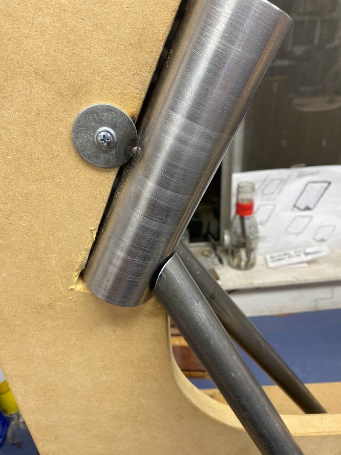
I do not have the liberty or budget to have CNC bent tubes, which is why I used the aforementioned tube bender. As a result, all the bends are done by hand, and have the associate imperfections of yours truly. The jig (pictured below) was supposed to hold the important bits in space (head tube at correct angle and centered in frame (important for no hands coasting and no pulling while riding). It was designed so the center board and rear board could be pulled out and reinserted as more items were added in for tacking and welding. Overall it did a good job at holding things square, but is most certainly a one time use item.
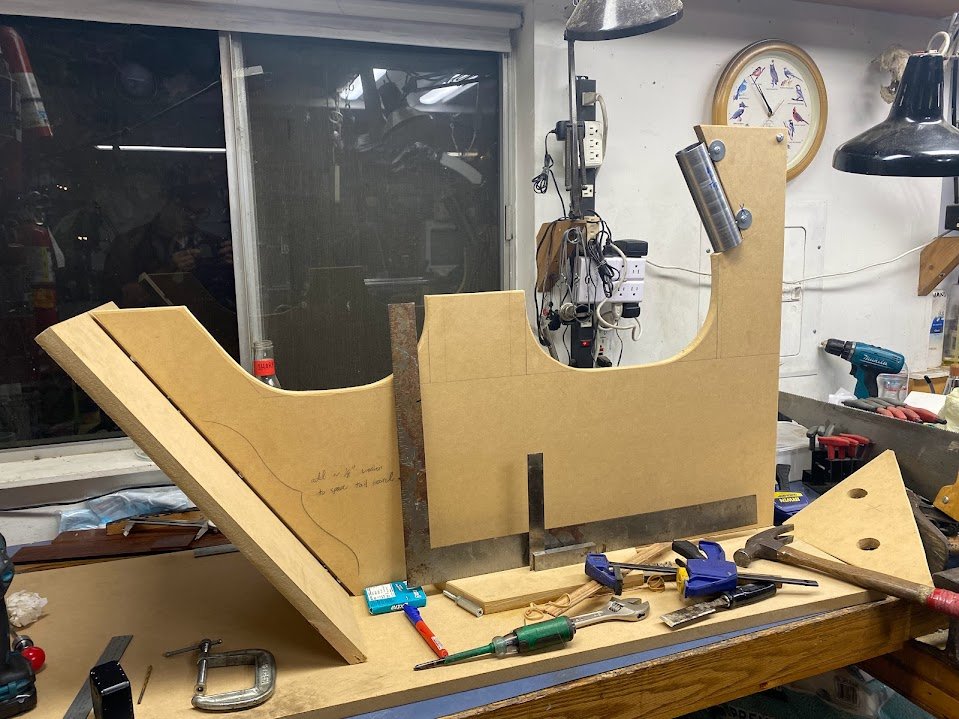
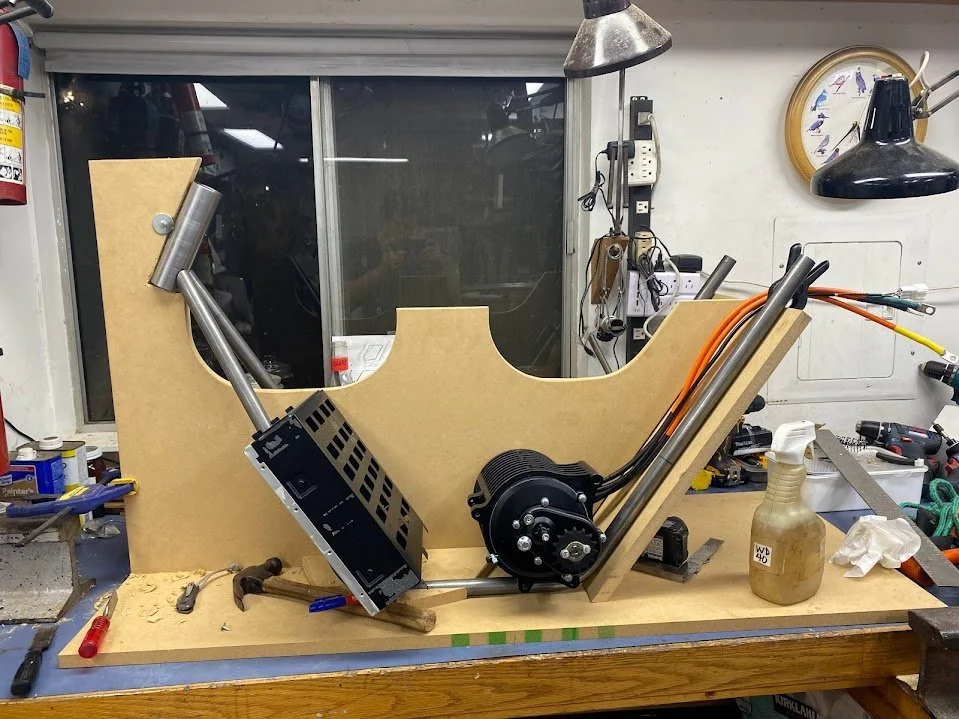
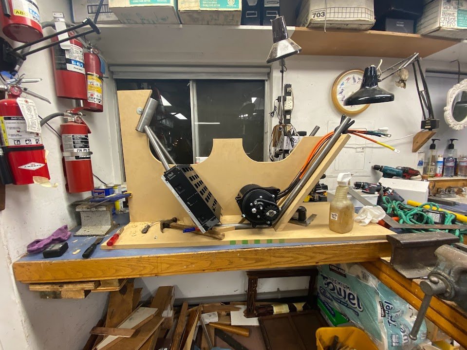
Motor Mounts!
All of my mounting plates and laser cut parts are duplicates, this was to keep cost per plate down, through SendCutSend, the cost of an individual plate gets reduced nearly in half if 2 are bought, and as a just in case, I get extras of each to keep myself from crying when something may or may not go wrong later down the road.
Below are the motor mounts placed in the frame, all lining up unusually well for a homebrew project of this sort, I guess it goes to show the power of CAD and prior planning. There is a 3rd set of scallops for another tube that is welded in space that was a real challenge to make work, but adds tons of rigidity to the already rigid motor mounts. Note the weird step in the rear of the motor mount, it allows the swing arm to fully travel/ compress with no interference (another win for CAD).
Below is the frame so far, as far as I can tell, everything is square, straight, and looking like it will come together fairly problem free. The chain line looks appropriate but I won’t know for sure until I get a chain on there. The 3rd member at the rear/ top of the motor mount lined up will with very minimal gap and was TIG’d into place. Around this time, I also placed my head tube support beam, also pictured below.
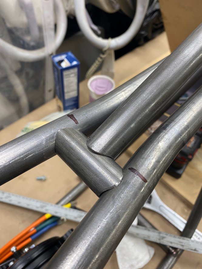
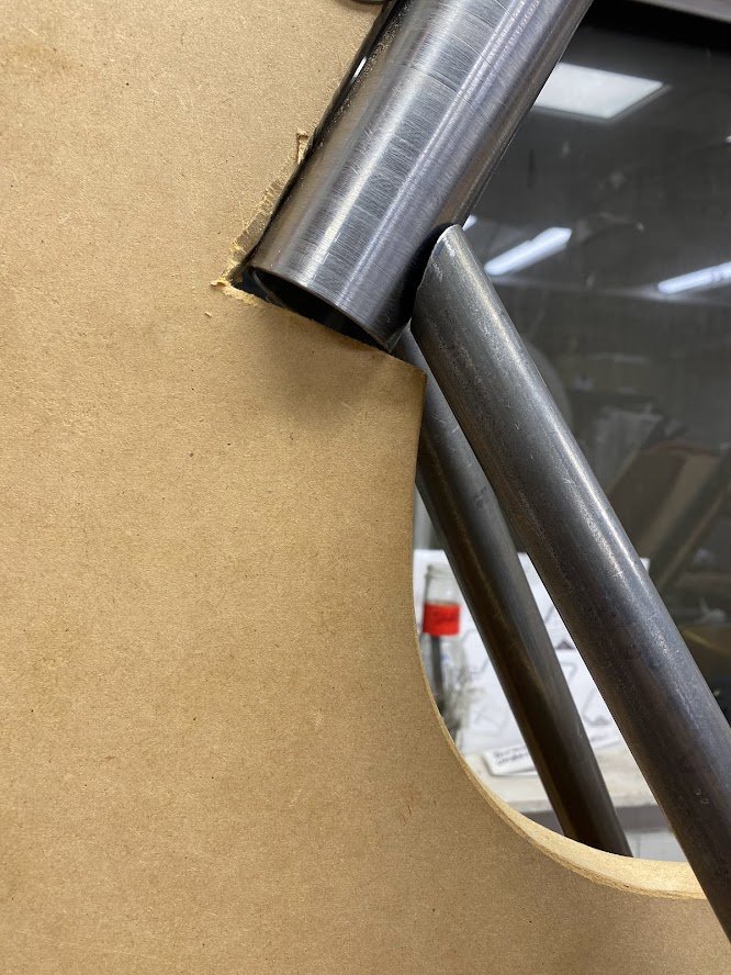
The photos to the right are just a little showing off of the fit ups I managed to get, some of the time, often after quite a bit of filing as the hole saw fixture I had is not the most accurate. The main thing is that the fit was close, and prevented contamination coming in from the backside. I was very pleased that I was able to lay down beads between the tight tubes where the two down tubes meet the headtube, and where the top tubes meet the down tubes.


