
The Mini Bike
So this time around, I’m, actually building a proper sized minibike with a gas engine, full suspension and a 1960s- 1970’s look to top it all off. This project was supposed to be my original quarantine project, prior to getting the OK to do the previously documented Jeep. As a result, this project immediately got thrown onto the back burner and got split into two sections, Quarantine 2020 and Winter Break 2020-21.
Goals
Build a minibike around standardized parts
Incorporate motorcycle geometry for handling and stability
Model the bike after a 1960’s minibike design
Responsibilities
Manage space constraints
Keep track of cost
Sell bike after building it
Time Line
May 2020
December 2020-January 2021
Summer Quarantine, May 2020
The plan was to reference this image of a 1960’s or 70’s Fox Minibike that had all the fancy bells and whistles that I wanted in my very own machine. The purpose for using this specific image was because it was the best side profile I could get. I printed it out as big as I could on an 8.5x11 sheet, and got to work scaling it around the tires, which in my case had to be 15’’ due to picking a standard pit bike wheel and tire combination. The angles were difficult to measure on such a small scale, and were thus finalized on a big 1:1 scale sheet of butcher paper.
As can be seen, the whole layout is drawn, using radius’ from my tube bending dies, instead of the original reference picture. This will better allow for part fitment later and makes this original sketch a more reliable reference material. Dots can be seen to the right of the frame sketch, indicating the points where the axles will go, furthermore dictating the angle of the head tube relative to the ground. It is recommended for motorcycles to use around 67 degrees from the horizontal, but due to a more pit bike type handling goal, I went with around 70 degrees for a more responsive feel. The contact patch (where the tire meets the ground) should be behind where the center line concentric and through the head tube crosses the ground, this was made sure of in the preliminary design.
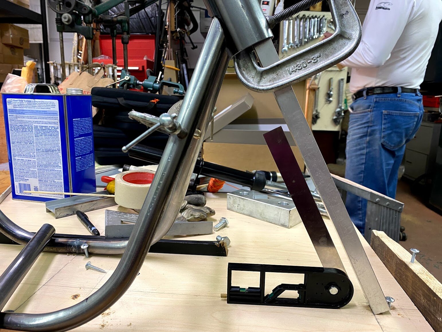
So there’s quite a bit that happened since I was kneeling on the ground with a sharpie drawing this. I began with bending some 7/8’’ steel tube to make the mirrored side portions of the frame. Two bends can be seen, welded at the middle (blue spot by the wood). I chose to construct these each out of two tubes in order to ensure that the rear bends were parallel to each other, and the front bends actually met at the same place. To be able to plan this an accurately execute this on my bender would be incredibly difficult, and even then, there would likely still be alignment problems. With this method, I had all the flexibility to match up the important weld joints. The continuous ovular hoop was bent from some 5/8’’ tube. I am mixing and matching my tubing diameters like this to achieve a desirable frame width. If I had used 7/8’’ tubing, the radius of the bend would have made the seat unusually wide and given weird geometry. The seat hoop isn’t under much stress compared to the rest of the frame. At the very front, you can see the about to be tacked head tube.
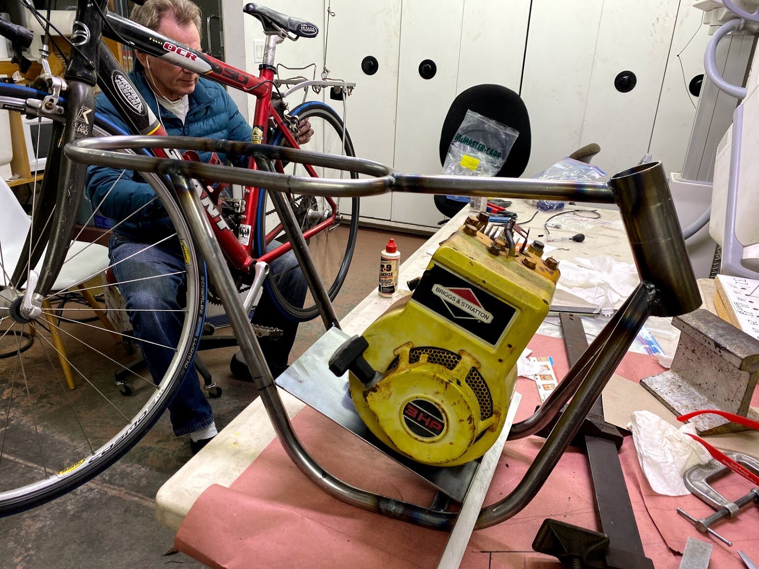

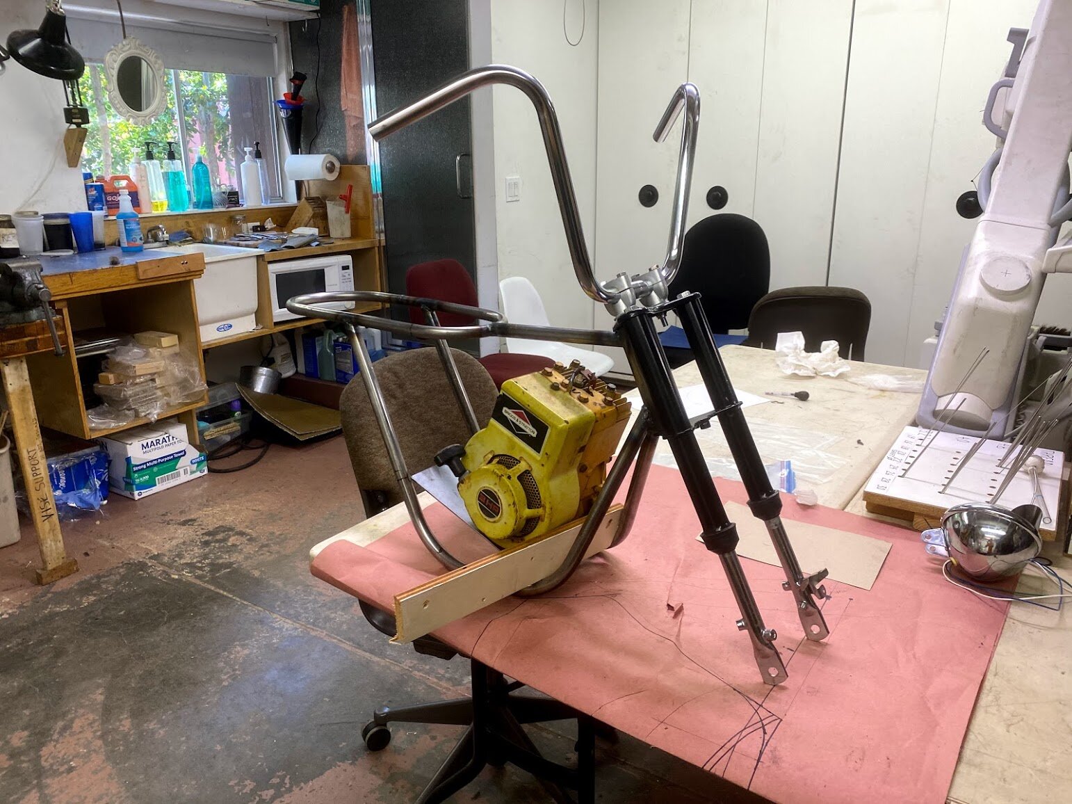
In the spread above, you can see the progress as I went along. The far left showing the correct head tube angle for the best handling. An engine is finally in! This is a 3hp Briggs and Stratton flat head engine, but its not very gutsy. It fits well inside the frame, but I got a 5hp engine later that far better suits the bike.
At this point, we have to get that power to the wheels (well, just one wheel in this case I guess). I have automatically opted for a torque converter. My findings in my Board Tracker project basically made the “torque converter” the best automatic style transmission for small engines (Its’ a CVT: Continuously Variable Transmission). Replacement belts are cheap, they require no oil, generate little heat, and give an initial low gearing advantage over an alternatives such as a “centrifugal clutch”. But I wanted this to be a built in transmission, not using the provided mounting plate that came in the kit. I would mount it directly to the frame via an integrated jackshaft.
In the first picture, you see me boring out some holes with a boring head. These are for the main drive bearings. Its hard to read the calipers, but they measure 1.375’’, I wanted it to be a near press/ interference fit, so got them an extra half a thousandths over or so. After pushing them in and out several times, they got a little looser.
I finally welded the little side plates to the sides of the engine mount plate. When they were welded, I had the steel rod you see poking out to make sure the plates were parallel planes, as well as to make sure the shaft was parallel to the engines crankshaft.
Finally I can show you wat the whole assembly looks like all together. You may notice the engine went from yellow to black, and grew slightly. This is because I finally got my hands on a 5hp engine. It is currently assembled with a custom machined drive shaft I made, picture below. I cut some standard 5/8’’ coarse threads on the lathe, and turned a groove at the opposite end for a snap ring. I finished it with a 3/16’’ key along the entire length.
So this is as far as I got before the Jeep took over. After this initial 2-3 weeks of progress, this project was not touched until the following Winter Break.
Winter Break, December 2020 - January 2021
Upon returning home for break, I immediately whipped up this rear swingarm, it looks very basic, slotted drop outs for chain tension, above those slots, tapped holes to mount the shock absorbers, and a full length tube for the pivot. The tubes are bent in an “S” shape to go from the narrow lower frame section to the wider pit bike hub. It also is visually appealing and gave me another excuse to use my tube bender.
Here is is bolted to the frame, the slop in its width an be shimmed with washers, allowing for a rattle free fit. The purpose of using a full length tube for the pivot was to reduce pressure (large contact patch) and create a space that could hold grease. This allows it to be smoother, and serviced less often without the need for brass bushings or bearings. In reality, with the springs being mounted so close to the rear axle, with a fairly vertical shock absorber, there such a relatively small amount of force pushing and pulling on the pivot axle.


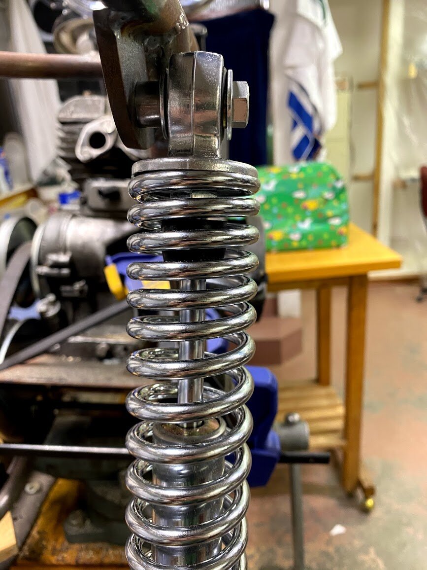
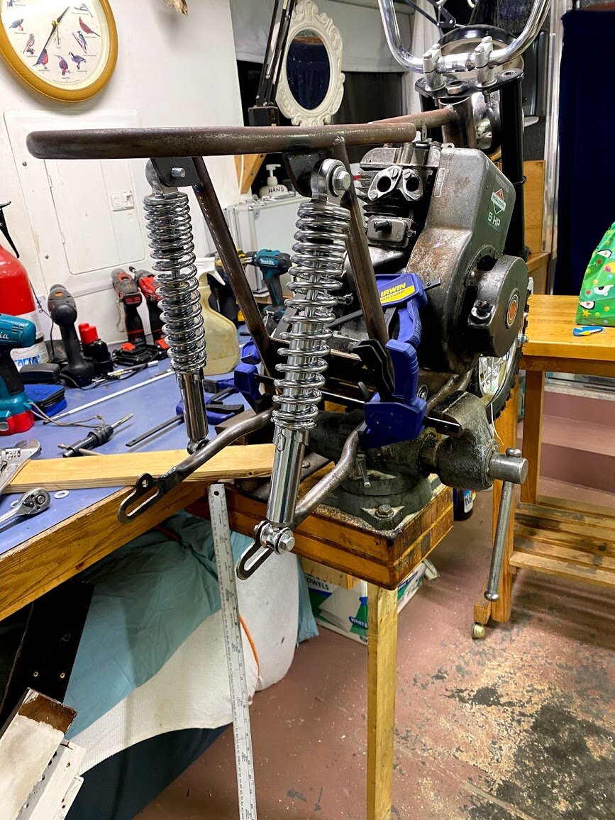
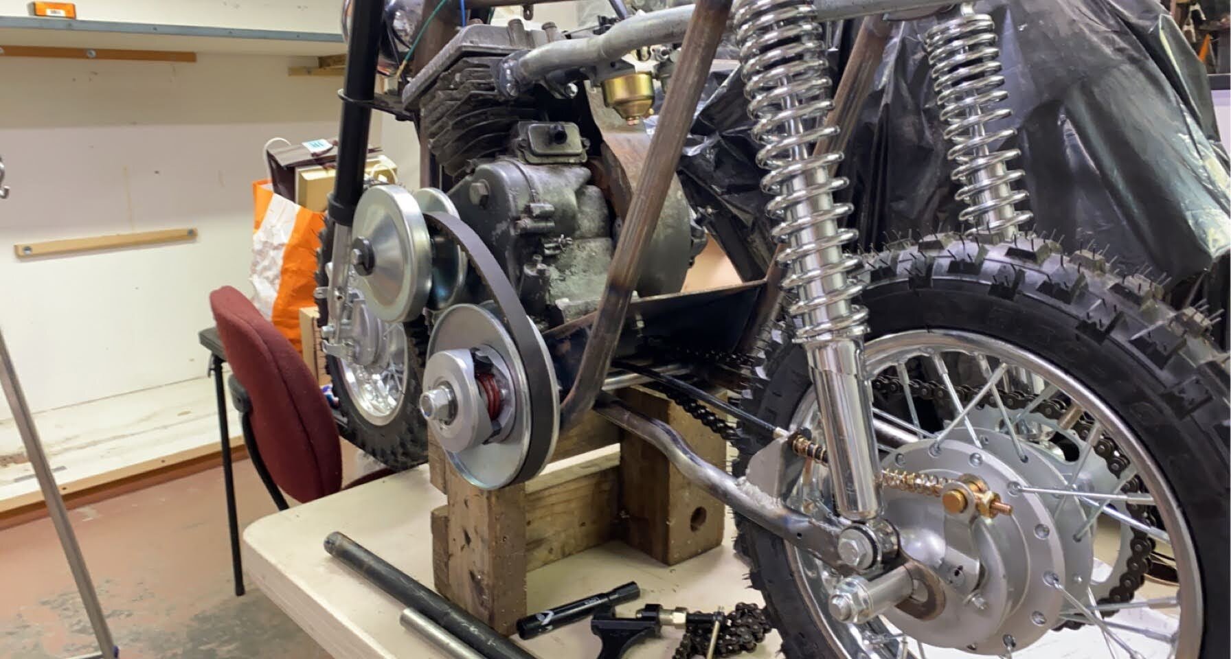
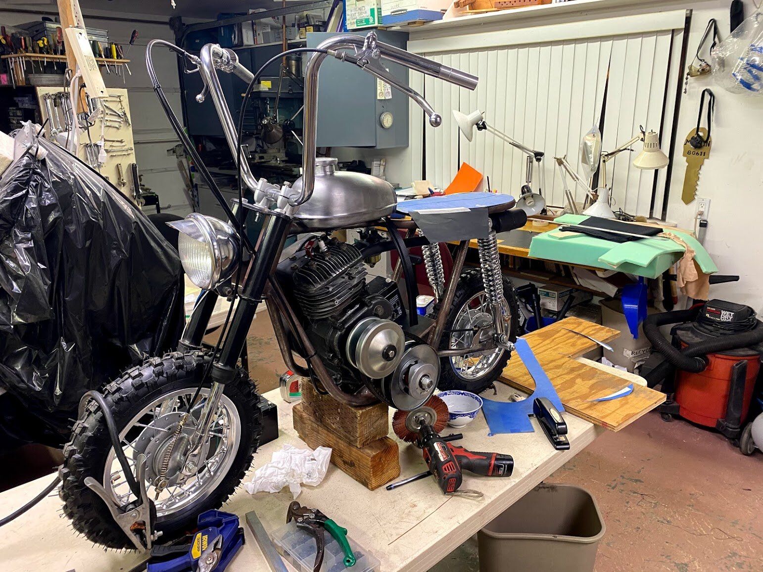
Above is the majority of the work that had to be done for the rear end of the bike. Wheels and tires were mounted, and a brake cable mount was welded to the swing arm to allow the cable to be pulled so I can stop. There is a quick comparison highlighting my progress to my reference piece, and overall, it is coming along well, the proportions are spot on, and the flowy handlebars gives it the vintage look I am after. The front shock absorber is a cheap unit off of a Honda pit bike. It fit this bike too well, and at such a low price, I couldn’t justify coming up with my own version of front suspension. With the handlebars mounted, I could add the break levers, and connect my twist throttle.
Sewing Time
Every cool vehicle needs its unique form of seating. Unfortunately Custom vehicles don’t use anything standard, or at least not a seat. Upholstery is a trade that is expensive to outsource, and furthermore, something I’ve always wanted to learn. I would say I’m pretty good at design and fabrication, but upholstery is an uncharted territory for me. At the end of it all, I was very satisfied and proud that I was able to learn how to do such a thing.
Well, where do we start? The answer is Craigslist. I needed a sewing machine before we could start sewing. After a few searches, I found one for $30, it was a Japanese “Empire” unit from the 1960’s that looked suspiciously identical to a “Singer” from England. The seller said it worked, and that was good enough for me. A half hour drive later and I was now the proud owner of my very own sewing machine. The machine I have pictured is not exactly the one I got, but aside from the color and the name badge, it is identical in every way.
After watching countless hours of automotive upholstery videos, I got the theory down of oversizing the pieces cut, purpose behind thread size, as well as difficulties of using thicker material on a smaller machine. All that there was left to do was practice on some scrap pieces, and to just do it.
First started by making a template of what I want in flattened form. Its hard to think about how it fits together, but in the end its sort of like sheet metal work.
Here’s the template against the pieces I stitched together. It acts as a guide and gives a good estimate of what the final size come out to.
This is the near final outer cover, ready to be flipped inside out to be attached to a wood backer with lots of high density foam between. The stitch seam, which in this case follows the shape of an upside down “U” uses up material, highlighting the importance of planning ahead and making sure to have enough sacrificial material.
The final seat! Its quite satisfying to see it mounted down, it slopes in and meets closely with the gas tank giving it a very satisfying look. If there was anything to redo on this, it would definitely be the choice of foam, it was not nearly dense enough, and I would most definitely opt for dedicated automotive foam in the future.
Carburetor, Paint, and Final Assembly
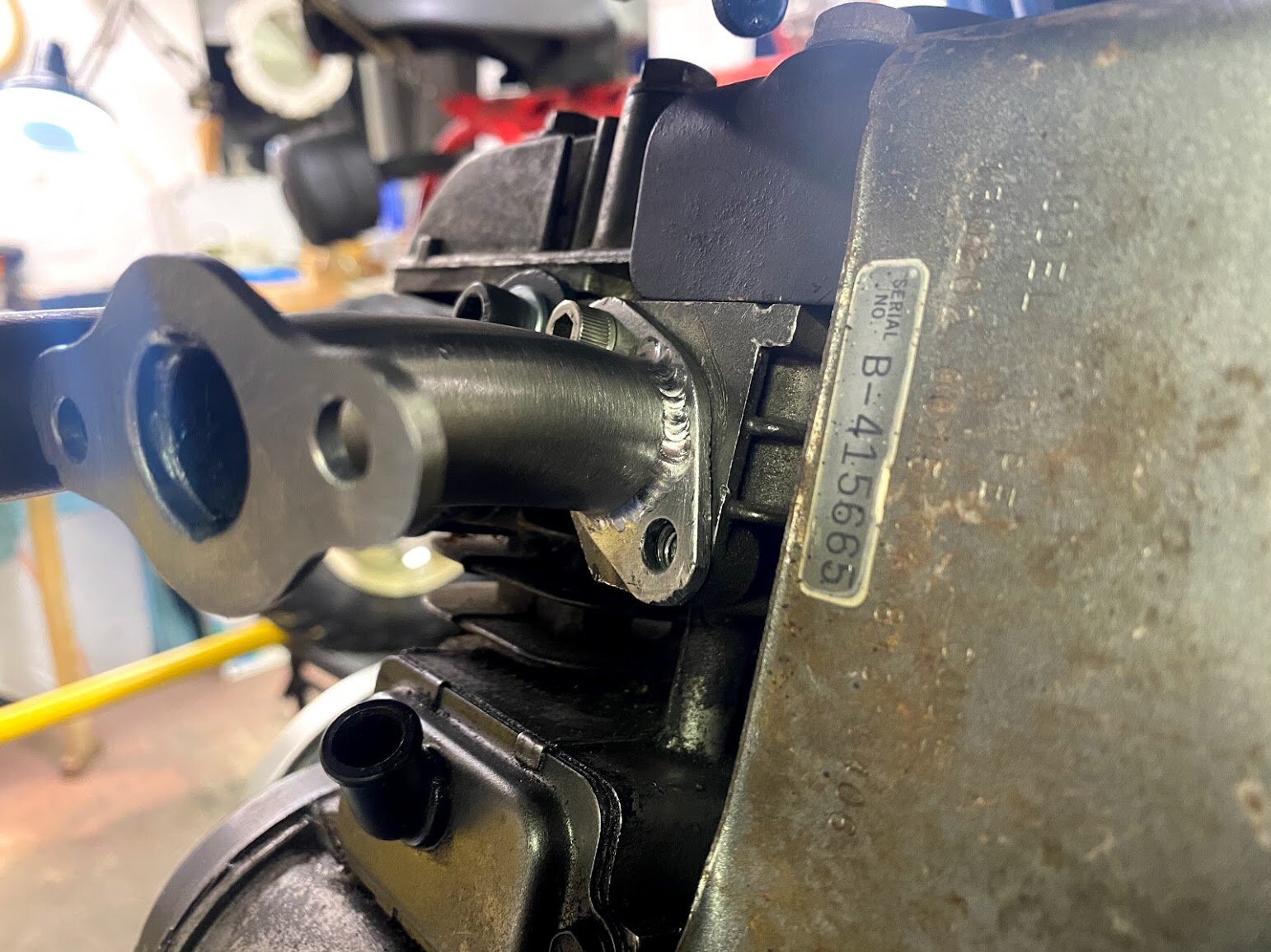

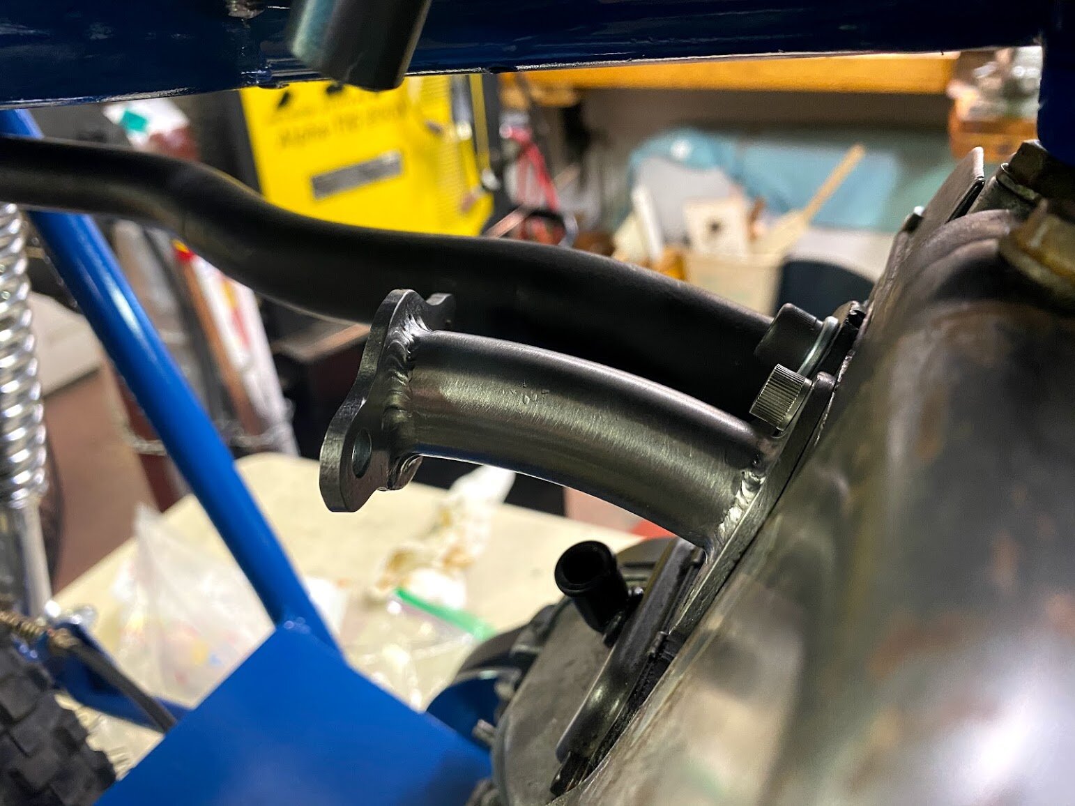
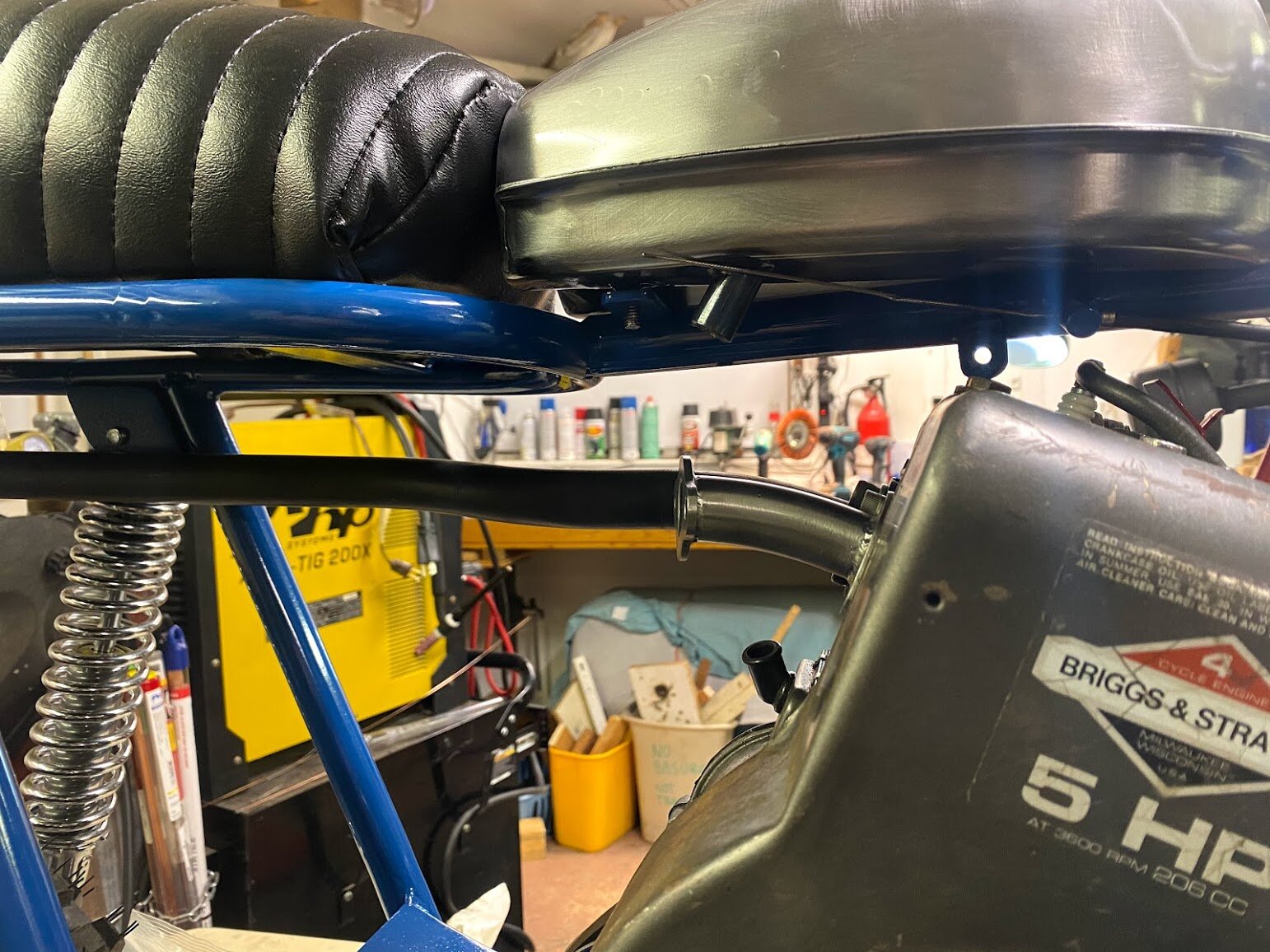
The issue of fueling the engine still has not been discussed. Because there was nothing available for my engine in its orientation, I had to make an intake manifold myself. I drew out the shape of the flanges using the corresponding gaskets for each side. I then used a plasma cutter to cut them out, and ground them to final shape on a bench grinder. I went to the scrap bin and found some tubing with approximately the correct curve. I tacked them while they were mounted to the engine block to ensure that the face the mounts to the carburetor was vertical relative to the ground. I then made a final pass with the TIG welder.
Everything was stripped down, gone over with steel wool and acetone before it was given a few thick coats of “Royal Blue”. There was nothing surprising about this process, but it was very satisfying to do
All that’s left to do is finally assembly! After a few tests rides, I got a top speed of about 40 miles per hour. This number is definitely being bottlenecked by the carburetor. When I was buying the carburetor off Amazon, there was no specification for which engine it was for ( a wide range of Tecumseh carburetors use the same casting between 2hp-9hp engines). I need to get the carburetor with a larger intake port and venturi. Despite this, he bike scoots around great. It doesn’t throw its chain off, the suspension is plush, and the steering response is great for putting around town.
Findings
This project is the first where I truly designed and built the frame in such a way that could considered a mainstream product. All the considerations were made to ensure the final result look and felt mass produced. Of all my work, this project certainly has the highest level of quality to time invested, but every one of my most recent projects are associated with that feeling, as they are summations of my past experience and learnings. This project stands out to me because it is one where I have been put in a position where the only option is to learn. Every time someone does anything, they get a little more in tune with whatever it is they are working on, even if they are well acquainted with that thing. Me running a lathe 5 years ago would be unrecognizable with me running one now, but that gradual increase of skill doesn’t feel as profound. Diving head on into a skill, in this case sewing, was an absolute treat, and I immediately was able to appreciate the skill it takes to sew. CAD (computer aided design) would have been neat to use, but it just didn’t fit this application. I’m the only one that needed how anything went together, and even for machined parts, I wasn’t sending anything to be done out of house so CAD wouldn’t have been useful for even precision parts.


